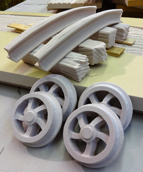
Today was a busy day but I couldn’t resist working just a little on the Lucky Jim Mine sign. The MultiCam was busy routing exterior moldings for the house but as each file finished I snuck in the railroad wheels and tracks on what would have been scrap. I actually ran the wheels twice as the first time they were simply too big for the sign I was building.
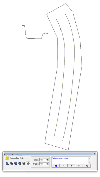
I also built the file for the track. It was a quicky.
The vectors were simple. Two parallel rails would form the bent track. The other vector required was the profile of half of a cross section of a train rail. I used the sweep two rails command, and followed the prompts


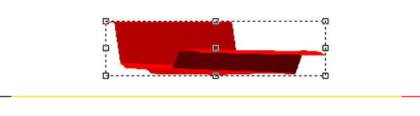
When it performs the task it shows black until I hit the render button. Meshes show up red. Meshes cannot be tool pathed. We first have to convert them to reliefs.


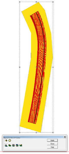
Then I selected both the relief and mesh to light up the mesh/relief merge button. In this case I could have used either the add to relief of merge highest.

When I render after merging the mesh and relief it comes out as splotchy red/yellow. I can then move/delete the mesh.
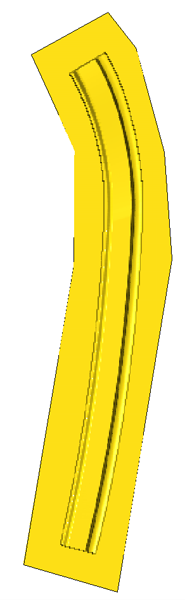
I duplicated the relief and flipped a copy for each rail to create the two halves of the rail. I tool pathed it using a 3/8″ ball nose bit with a 90% overlap. This would give me the rounded inside corners I wanted.

I used a five minute epoxy to glue the two halves together.