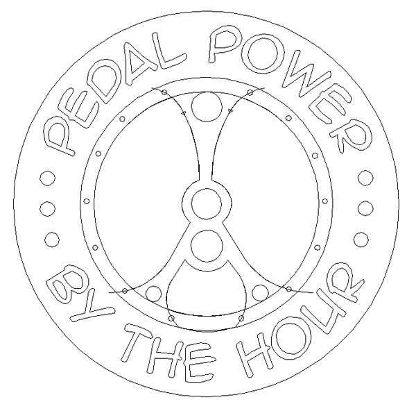
The lettering and basic shape of the sign was done in Illustrator. I then imported the ai file into .
Using the drawing tools I created the basic fancy frame to support the gears. I also added the borders and rivets around the outside.
Creating the gears was pretty simple. I first drew a circle, then a rectangle. A second box was drawn as a measuring device for the next step. I centred all of the pieces with each other.
I then used the point edit tool to bend out the sides of the longer rectangle using the smaller box as a guide. There are more accurate ways of doing this procedure but this was plenty good.
I then used the array tool to space out the pieces at the right angles.
And finally I combined the vector shapes to create a gear outline.
The inside spokes used some of the same methods. Creating multiple copies using the array tool I used a value of 180 degrees. This created one extra copy of the rectangle but rather than do the math tp calculate the angle I needed to start and finish it was simpler to just delete the extra rectangle and then centre all the pieces in relation to each other.
I used the combine tool with another circle (not shown) to create the spokes of the gear.
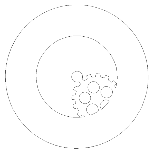
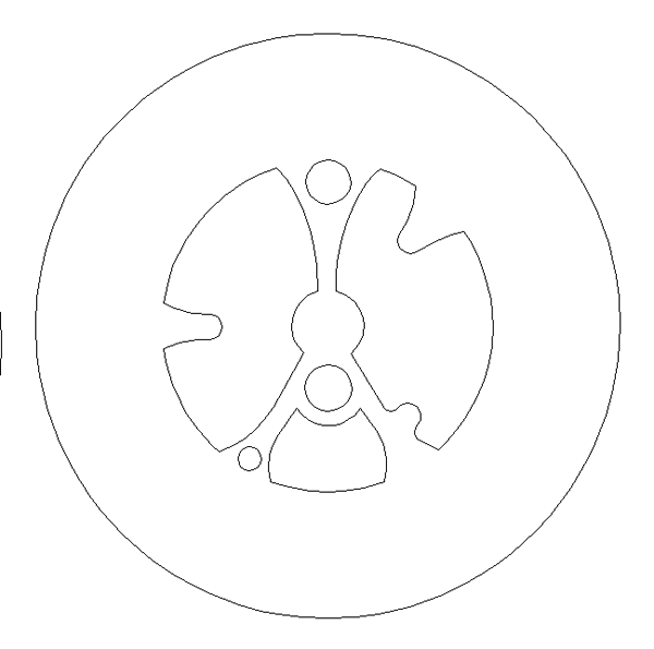
Once I had all of the primary vectors built it was time to decide how many layers the clock would take to convincingly build. I decided five would do it. I then separated, duplicated as necessary and then combined the components in each layer to form the vectors I needed to create the routing files. Here’s a screen shot of each layer’s vectors. I still have to add the vectors to route out the space for the metal frame in the middle sections.
