First we need to make note that there are different versions of EnRoute. To create 3D files you need EnRoute Pro. I use the latest version EnRoute Pro 5. Earlier versions will do most of the things the later versions do but the speed of the program has really gotten much better of late.
When I fist opened EnRoute I had never created a vector, never mind a 3D file so it was absolutely scary and overwhelming. In the next series of posts I’ll be doing my best to taking the mystery out of creating 3D files. I’ll speak in plain english too and may get some of the tools proper names wrong. But I do know what they do, even how to do some things that aren’t in any manual.
The key to learning enRoute is doing things again and again until you know them. Don’t try and learn too much in one sitting. I know my brain can only absorb a few things before it goes to mush.
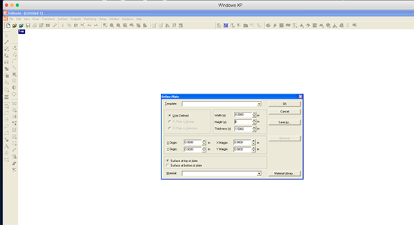
Then you open the program the first thing you need to do is define the plate. Go to the top right corner and click file>define plate.
There are lots of boxes to fill out but you only have to deal with there at this point… width (how wide is the piece you are creating) Height (how tall is your piece?) and thickness (how thick is the material you are planning to cut?) Usually I make the first two measurements a little larger than the sign I am making.
The tools can be rearranged how you like to use them and will be there the next time you open the program. The tools are grouped to make them easy to locate. I like my vector drawing tools on the left side. These tools are used to create new vectors which will define the reefs you are creating.
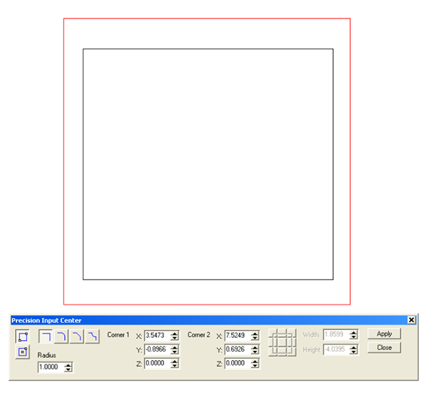
I used the rectangle tool to draw a box inside my plate. If I wanted it perfectly square I would have used my shift key at the same time I was drawing it. I could have entered the exact parameters in the boxes too to get precise results although I have yet to do it this way. You will note some options as well including adding a radius, chamfer or profile to the corners of the box and using the radius parameters to define the radius.
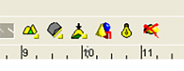
Once a closed vector is drawn we can create our first relief. I’m going to keep it simple and create a flat box. First I need to select the icon that opens the create relief function. Its the little yellow loaf of bread. Its actually called create a relief button.
Once you select the create a relief button the menu box will open. This can be used where it is or dragged near the plate where you are working. I tend to do the latter because I do a lot of screen shots for this blog.
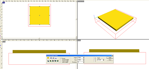
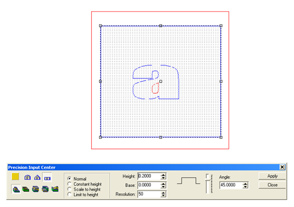
There are many options within this menu. On the left are the functions. The top row has three. On the left is the dome tool. This creates round reliefs. The middle one creates bevelled reliefs and the one on the right (this one is selected in the picture) creates flat reliefs. If you hover your mouse over them they will tell you what their name is.
The bottom row of the right hand sets of buttons also is very important. The first, on the left is add-to (or create) a relief. Next is the subtract from a relief. The middle one is merge highest. Next is Merge lowest. and finally is replace relief. When we are building new reliefs we use the first button most of the time. Create or add to relief.
The center column has four functions. Normal (we use this one most of the time) The there there are used with the bevel and dome tools to create particular effects. We’ll deal with these in later lessons.
The third column has three boxes which we can change as we please. The first is the height. If we put in a value of 0.5 the height of the relief will be 0.5. The middle box labeled “base” is the amount you wish the vertical sides of your bevel or dome to rise BEFORE the top sloped portion begins.
The last box is resolution. Many people freak out and worry about this box too much. a resolution of 50 dots per inch is plenty for routing – unless you are using a teeny bit to cut jewelry of something else real tiny. To give you a point of preference… if you are using a 1/8″ bit with a zero overlap your DPI is actually 8 points per inch. I’ve never used higher than the stock setting of 50 on my work. A higher resolution will certainly bog down you computer on larger files.
So for this excursive I selected the box I had drawn, opened the create a relief box (little yellow loaf of bread), selected the create a flat relief button and ADD-TO (or create a relief. Then I entered a value of 0.400 inches. This will create a flat relief that is 0.4 inches tall.
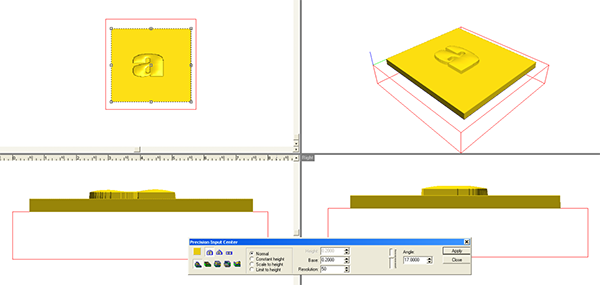
Now it is time to check to make sure the program did what you thought it was going to do. Select the icon that looks like a light bulb. This will render your object. Also double click on the blue box that says TOP (view) This will give you the TOP, FRONT, SIDE and a three quarter perspective view. When I checked the rendered views I found that the file had done just what I wanted. I then double clicked the TOP box once more (which made it back to only the top view) I also clicked on that light bulb once more to hide the render so I could see my vectors once more.
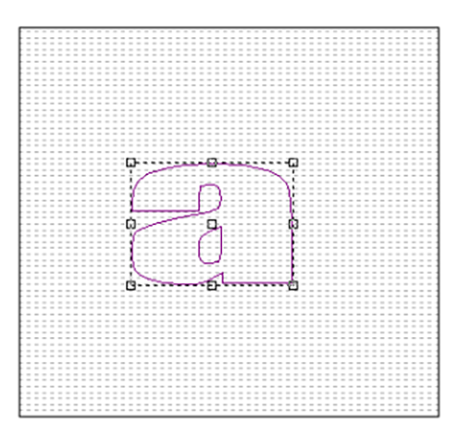
Now I want to modify my relief. The relief if that box which is 0.4″ thick. I’ll do that by drawing an ‘a’ on top of the box. In the menu there is a letter ‘A’. This is the type tool. If you hold it down there is a second hollow ‘A’ which converts the lettering you have created into vectors.
So I typed an ‘a’. This was sized and positioned inside the box that defined my relief. The letter appeared in a burgundy color which indicated it as type. Before we can use it I had to first convert it to vectors. (see above)
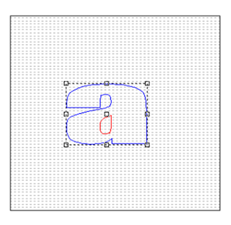
When I convert it to a relief it changes color. The outside vector (shape) is blue while the inside vector (hole) is red. This difference in color is very helpful as we get into more complex features down the road. Just understand that in this case the Blue shape will affect the relief we are modifying while the red vector (hole) will do nothing.
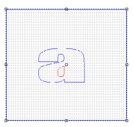
To modify the relief I first need to select the relief. Then I select the vectors which I will use as masks to define the areas I wish to modify.
Once I have selected the items I wish to use I push that yellow loaf of bread again to open the relief box. In the left side I punched the flat relief button and the ADD-TO button. In the middle column I do nothing. I type in a value of 0.2 inches. The angle does not matter since I am not creating any angles. Then hit apply. Think about what you wanted to happen.
Then render your object. (light bulb)
Now double click on the TOP button (top left corner) to render the front, side and three quarter views. I got what I was expecting and so I could go back to my top view for the next procedure.
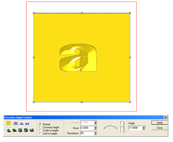
By clicking on the icon with a red X (delete reliefs) you will go back to just the vectors. Now it is time to try something else. First create a flat relief (as above) We’ll use that same ‘a’ vector to modify the relief but this time we will use the level tool. It has a base of 0.2″ which means the sides of the letter are 0.2″ tall before the bevel starts. Then I set the angle of the bevel at 17 degrees. hit apply. Render the relief and check all of the views to make sure you got what you wanted.
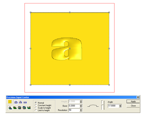
Take it back to just vectors. Then start one last time. This time we’ll do the same thing using the dome tool.
Don’t forget the render and check it in the multiple views to make sure you got what you wanted. If it turns out weird it is because something wasn’t quite right. Go back (hit the undo button) and do it again until you get what you want and also understand what happens.
