So you’re working on your surface model, and you are trying to get everything to match up nicely, usually to either G1 (tangent) continuity, or G2 (curvature) continuity. You think things look pretty good, you join them all together, you run ShowEdges to see if your model has any naked edges……and then you use Zebra to check that your edges are continuous in the way you desire. Which, frankly, I think is completely nuts. Allow me to explain. Here’s a wingtip I made recently: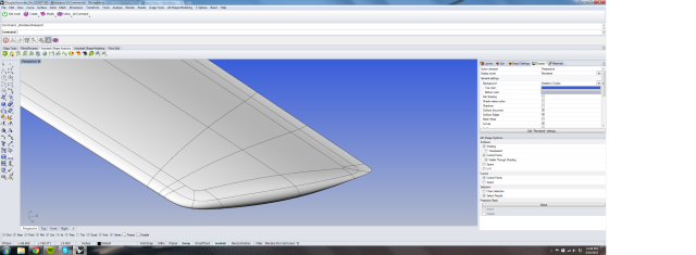
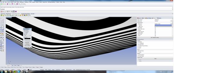
It looks very smooth and nice, but……do I know it’s smooth and nice? If I use Rhino’s Zebra analysis tool, I get something like this:
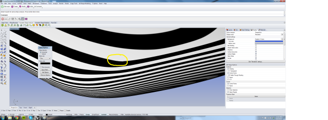
Well yeah, that looks good….I think? Right? Wait! What about this little burble here:
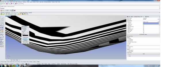
What’s that? I mean, if you read through the Rhino Level II training material, that would indicate that your model might even have a naked edge there, despite the fact that we know there is not a naked edge (because you always run ShowEdges after you join your models together right?). It’s at this point that one usually goes onto the Rhino forum, start a thread about continuity and someone points out that hey those Zebra results are totally dependent on your mesh settings. Oh right! To illustrate that, let’s see what Zebra looks like with the mesh settings all the way to the most coarse:
Clearly, my model is a piece of garbage! Except, it’s not. In fact it’s the best wingtip I’ve ever made. So, to review, checking the continuity of your surfaces in Rhino involves jacking up the mesh settings to such a degree that you’re totally (pretty?) sure that if you see something it’s the surface and not the mesh, and then zooming way in on all your seams, and visually inspecting them for breaks in your Zebra analysis. This sounds crazy, no? I mean, if only we lived in a day and age where we could program some sort of fancy adding machine to do mindless trivial tasks for us and give us nice numerical results to work against, instead of squinting and zooming and changing our mesh settings, and then squinting again…..more zooming……etc. Good news! We do live in such a day and age. I’ve been using Autodesk Shape for a few years now, and I have to say it’s fantastic. There are a whole host of tools used for both analysis and surface generation/editing, but the one I use for analysis over and over and over is called Global Matching Analysis, and let me tell you it’s wonderful. Instead of making you do the whole Zebra dance I outlined above, it actually measures and computes the continuity between joined edges, and gives you very sensible table of results. Allow me to illustrate. If you start the tool, select your geometry and then click Apply in the box, you’ll get something like this:
There’s a lot going on here, but I assure you, it’s very usable. See near the top where it says “No. of Points?” That’s how many samples it’s taking along each edge. 50 is plenty for most applications. Now let’s star by seeing if the model is tangent continuous where I expect it to be so. First, you have to ask yourself “what do I consider to be good enough for tangent continuous?” We’re talking degrees here – how many degrees from 0.0 can adjacent surfaces be and still be considered tangent? I like 0.5 personally. So I set the low end threshold at that using the Range Min. setting. The top end setting (9.0 in this case) can be thought of as the “over this setting, and it’s intentionally not tangent continuous” setting. Like if you had an intentional sharp crease, you would want a way of excluding that edge from the report, since you have not expectation of that being G1. Now, click the “Defectives only” box under Results. Here’s what you get:
Only two edges here are not tangent, but let’s take a look:
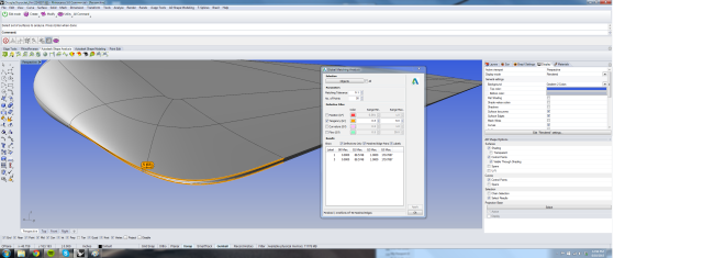 Right! These edges are part of a surface that transitions between the blunt trailing edge and the smooth shape of the tip. There is no expectation of these being tangent, and since they are transitioning from G0 (positional) to G1 (tangent) of course they are going to set off an alarm. In short, everything that I expect to be tangent IS. All is well! Now, checking for G2 (curvature) continuity, we can set the upper and lower limit just like with Tangency Range Min/Max. I typically leave it at the default of 0.5/1. In this case, anything less than 0.5…..curvies? I actually don’t know what the units are here, in fact it might be unit-less, but really what it comes down to is the rate of change between adjacent surfaces. So if the delta of the rate of change is less than 0.5, I’m calling it good. For this model I get this:
The majority of the edges are indeed G2. How about that one at the back? Well, to generate that surface I used the Shape Surface Blend tool, and I was not able to get the overall shape I wanted with it set to Curvature on the edges. We could go pretty deep down a rabbit hole here, but suffice to say I did not expect those particular edges to be G2, and I’m still very happy with my wingtip. I’ll be doing a whole set of posts over the next few weeks about Shape and using this wingtip as an example of cool stuff you can do with it. Hope you found this useful, and hopefully you can free yourself from the insanity of Zebra analysis!
And, just in case you’re wondering – I’ve never been given a free copy of Shape, I’m simply a user of it, a very happy user.
